
OFFSET DISC DESIGN
OFFSET DISC DESIGN
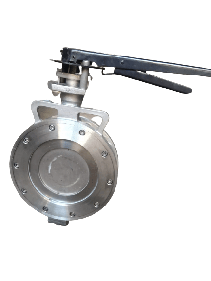
We, “Flow-Tech” are a leading manufacturer and Exporters of OFFSET BUTTERFLY VALVE. Offset
Butterfly valves means that the stem does not pass through the center line of the disc, but insteadbehind it, opposite of flow direction. When the stem is located right behind the center line of the disc,
the valve is called single-offset. This design was developed to reduce the disc contact with the seal
before full closure of the valve with the aim of improving service life of the valve. Today, single-offsetvalves have given way to double offset and triple offset butterfly valves.
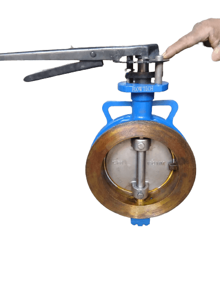
In a Double-Offset Butterfly Valve, the stem is located behind the disc with an additional offset to oneside. This double eccentricity of the stem enables the rotating disc to rub over the seat for only aboutone to three degrees.
In a Triple Offset Butterfly Valve is often used in critical applications and is designed similar to adouble offset butterfly valve. A triple offset butterfly valve is more efficient and allows for less wear. Triple offset valves are often made of metal seats to create a bubble-tight shut-off. The metal seatsallow butterfly valves to be used in higher temperature ranges.
High performance butterfly valve designs use the pressure in the pipeline to increase the interferencebetween the seat and the disc edge. These butterfly valves have higher pressure ratings and areprone to less wear.
“Flow-Tech” OFFSET BUTTERFLY VALVE design is developed with following and using international Standard for Having an International Competency with Global Manufacturers.
We “Flow-Tech” follow an international standards and designs to get 100% superior quality withworkmanship & service to maintain trust of our Clients and repeat order.
| TECHNICAL DETAIL | |
|---|---|
| DESIGN TYPE | OFFSET DESIGN DOUBLE OFFSET DESIGN TRIPLE OFFSET DESIGN |
| MFG. STANDARD | BS 5155, API 609 & AWWA 504 |
| TESTING STANDARD | API 598 / BS 6755 Part-1 |
| FACE TO FACE STANDARD | BS5155,API 609& AWWA 504 / ANSIB 16.10 |
| PRESSURE & TEMPERATURE RATING | ASME B 16.34 |
| PRESSURE CLASS | 150#, 300#, PN10, PN16 |
| VALVE SIZE | 1 1/2” To 40” (40 mm TO 1000 mm) |
| ENDCONNECTIONS | WEFER TYPE |
| FLANGE DRILLING | 150#, 300#, PN10,PN 16, BS10TABLED / E /F /H |
| VALVE SEAT LEAKAGE | CLASSVI (Zero Leakage) |
| MATERIAL OF CONSTRUCTIO | CITOIS210GR.FG200 ASTMA 216GR.WCB ASTMA 351GR.CF8 / CF8M/ CF3/ CF3M |
| OPERATIONS | HANDLEVER (WRENCH) /GEAR PNEUMATIC/ ELECTRICALACTUATOR |
| FACE TO FACE DIMENSIONS | ||
|---|---|---|
| INCH | MM | 150# |
| 11/2" | 40 | 35.0 |
| 2" | 50 | 44.0 |
| 2.5" | 65 | 46.0 |
| 3" | 80 | 46.0 |
| 4" | 100 | 52.0 |
| 5" | 125 | 56.0 |
| 6" | 150 | 56.0 |
| 8" | 200 | 60.0 |
| 10" | 250 | 68.0 |
| 12" | 300 | 78.0 |
| 14" | 350 | 78.0 |
| 16" | 400 | 102.0 |
| 18" | 450 | 114.0 |
| 20" | 500 | 127.0 |
| 24" | 600 | 154.0 |
| **For More & Higher Size, Please Contact Us | ||
| TEST PRESSURE | ||||
|---|---|---|---|---|
| CLASS | BODY HYDRO TEST | SEAT HYDRO TEST | ||
| PSIG | KG/CM2 | PSIG | KG/CM2 | |
| 150# | 213 | 15 | 142 | 10 |
| PN10 | 213 | 15 | 142 | 10 |
| PN16 | 300 | 21 | 213 | 15 |
| *Pressure Testing Time Will be 15 Sec. *Test With Water only. | ||||